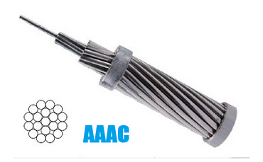
Conductor(AAAC) have been widely used in power transmission lines with various voltage levels,and also used in power lines across great rivers,heavy ice area,and other places special geographical characteristics.The conductor have excellent advantages of high strength,large current carrying capacity and good catenary property as well as wear-resistance,anti-crush and corrosion-proof with simple structure,convenient installation and maintenance,low cost for the line,large transmission capacity.
Standards
GB/T 1179-2008, IEC 61089, EN 50182, DIN 48201 Part 6, BS 3242, ASTM B399, NF C 34-125
Specification
AAAC conductor are made out from aluminum-magnesium-silicon alloy of high electrical conductivity (min 53% IACS) containing magnesium (0.6-0.9%) & silicon (0.5-0.9%) to give it better mechanical properties after treatment. AAAC conductors are made out of aluminum alloy 6201. AAAC conductor has a better corrosion resistance and better strength to weight ratio and improved electrical conductivity than ACSR conductor on equal diameter basis.
Description
| Density |
2.70 kgm/dm3 at 20°C |
| Coefficient of Linear Expansion |
23 x 10-6 / °C |
| Resistivity |
0.0326 Ohms mm2/m at 20°C |
| Constant Mass Temperature Coefficient (a) |
0.00360/ °C |
| Material |
Heat treated Al. Mg. Si. Alloy |
Technical Characteristics
| AAAC Technical Characteristics Based on Standard BS 3242 |
| Code name |
Nominal aluminium area |
Stranding and wire diameter |
Sectional area |
Approx. overall diameter |
Approx. mass |
Calculated D.C. resistance at 20oC |
Calculated breaking load |
| mm2 |
No./mm |
mm2 |
mm |
kg/km |
Ω/km |
kN |
| OAK |
100 |
7/4.65 |
118.9 |
13.95 |
325 |
0.2769 |
33.3 |
| ASH |
150 |
19/3.48 |
180.7 |
17.4 |
497 |
0.183 |
50.65 |
| ELM |
175 |
19/3.76 |
211 |
18.8 |
580 |
0.1568 |
59.1 |
| UPAS |
300 |
37/3.53 |
362.1 |
24.71 |
997 |
0.09155 |
101.5 |
| AAAC Technical Characteristics Based on Standard DIN 48201 / DIN EN50182 |
| Code number |
Area |
Number of wires |
Wire diameter |
Conductor diameter |
Linear mass |
Rated strength |
D.C. resistance at 20oC |
| mm2 |
No. |
mm |
mm |
kg/km |
kN |
Ω/km |
| 35 |
34.4 |
7 |
2.5 |
7.5 |
93.8 |
10.14 |
0.9572 |
| 50 |
49.5 |
7 |
3 |
9 |
135.1 |
14.6 |
0.6647 |
| 70 |
65.8 |
19 |
2.1 |
10.5 |
180.7 |
19.41 |
0.5026 |
| 95 |
93.3 |
19 |
2.5 |
12.5 |
256 |
27.51 |
0.3546 |
| 120 |
117 |
19 |
2.8 |
14 |
321.2 |
34.51 |
0.2827 |
| 150 |
147.1 |
37 |
2.25 |
15.8 |
405.3 |
43.4 |
0.2256 |
| 240 |
242.5 |
61 |
2.25 |
20.3 |
670.3 |
71.55 |
0.1373 |
| 300 |
299.4 |
61 |
2.5 |
22.5 |
827.5 |
88.33 |
0.1112 |
| Technical Characteristics Based on Standard NF C 34-125 |
| Code number |
Area |
Number of wires |
Wire diameter |
Conductor diameter |
Linear mass |
Rated strength |
D.C. resistance at 20oC |
| mm2 |
No. |
mm |
mm |
kg/km |
kN |
Ω/km |
| ASTER 54.6 |
54.6 |
7 |
3.15 |
9.45 |
148.9 |
17.73 |
0.6042 |
| ASTER 148 |
148.1 |
19 |
3.15 |
15.8 |
406.5 |
48.12 |
0.2239 |
| ASTER 228 |
227.8 |
37 |
2.8 |
19.6 |
627.6 |
74.04 |
0.146 |
| ASTER 288 |
288.3 |
37 |
3.15 |
22.1 |
794.3 |
93.71 |
0.1154 |
-